
BEGINNING THOUGHTS AND IDEAS
I wanted a set of electronic drums. Not sure why, as I already had a nice acoustic drum set that I loved to play. Maybe it was to appease the family, and keep the so-called “noise” to a minimum. Maybe it is that I’m hitting that stage in life often referred to as the “middle age crisis.” Maybe it was because it was winter and I wanted something to do. Basically, all of the above. The following is the rabbit hole that I went down in my effort to obtain a set of electronic drums.
(Note: I did this build in 2011, and I am now writing about it in 2016 – I didn’t have a blog then! Therefore, I may not have included every little detail as five years has passed, and at my age, I can’t remember what I had for breakfast.)
Since nicer quality electronic drum sets cost in excess of $2000, I looked into alternatives and found much info on do-it-yourself edrum projects. There are Remo drum practice pad conversions, acoustic drum set to electric conversions, as well as building your own design wood and rubber pad sets. I Googled anything related to electronic drums. As I studied the info, I decided that doing a project from scratch, with newer materials was my preferred option. I wanted the edrums to sort of look like drums, so I settled on using new wood drum shells instead of converting and cutting an old acoustic set because they were cheap. Finding a good, used acoustic set was running into $300 and above, and I wanted to keep the cost low, as well as keep the size of my edrum kit small.
FINDING THE MATERIALS
Now on to ordering the materials. I needed everything! Shells for the drums, hardware, electronics, etc. I decided to look online for suppliers and found a company called drumMaker.net. This opened up a ton of possibilities for me, as they had all sorts of drum making materials. But it was for the acoustic drum set builder. I found the shells they had on their site to be interesting, but way too costly. So I ended up searching for drum shells and found a company called Keller. They supply many drum makers with shells. I ended up on their eBay store and found some items that I thought would work. I ordered (2) 14” and (4) 12” – 5 ply Keller Maple drum shells from Keller that I found listed as overstock for $160. This included shipping and cutting the 24” X 12” wood shell into 4 pieces. I plan on using the 14” drums for snare and kick, and the other four 12” drums for toms.
When I received the shells I got three surprises. The first – 5 ply shells are not very thick! I was starting to think that I might have trouble with a shell that thin. But in the end the shell thickness turned out not to be an issue. Thicker ply would have meant a much heavier drum. And since I was using a mesh head, I didn’t feel like the tension would be as high as a normal drum head would have to be.
The second surprise was I had requested that they cut the larger shell into four shells. This would give me four 6″ depth shells. However, when they came one of the shells was about 5″ in depth. After finishing the drums and mounting them, it is hardly noticeable. I use it for the first mounted tom.
Lastly, surprise number three was that they accidentally included another large shell that I hadn’t ordered! So now I had four 12″ toms, a 14″ snare, and the original 14″ shell that was planned to be my kick drum became a floor tom of sorts. The extra larger shell became my kick/bass drum.
I found another supplier, Drum Factory Direct that was somewhat cheaper for the hardware: the hoops, lugs, lug screws and bolts, and other mounting accessories. I decided to keep costs down I would use 8 hole hoops for the two 14” drums, and 6 hole hoops for the four 12” drums. Since I’m putting a non-functioning resonant head on the kick to hide the internal stuff, I’ll need three hoops and 24 (3 X 8) lugs and 24 tension rods. For the 12” toms, I’ll need four hoops and 24 (4 X 6) lugs and 24 tension rods. So, 48 lugs and 48 tension rods total need to be ordered. Each lug will require two lug screws to hold it to the drum shell, for a total of 96. This is getting expensive!
For the piezo triggers, I found a seller from Germany on eBay that not only sold the piezos, but also the foam contact cones as well. Big time score on that, because I wasn’t sure how to find the foam and get it into a cone shape that is typically used in these projects. I don’t think it has to be coned shaped, but if Roland engineered theirs to be that way, I think that is why most people are trying to copy the design. The kit has 5 pre-attached cone piezos for the toms/kick, one more sensitive cone/piezo for the snare, and 5 additional piezos for dual or rim triggering.
For the drumheads, I wasn’t convinced that DIY mesh heads were going to be strong enough to withstand even my weak drumming, so I invested in Pearl mesh heads. The Pearl heads were designed to be quiet, and hopefully they will hold up.
Deciding on mounting hardware meant also considering what to mount them to. After looking at the cost of Gibraltar and Pearl mounts, even the used stuff, I decided to go a different route. I found that Musician’s Friend had a two for one deal on Sound Percussion cymbal stands. Several reviews indicated that the stands were quality and sturdy. I had the bright idea to use a DW drum mount and attach it to the stand. This will give me two drums mounted to a cymbal stand. But a trip to the Home Depot got me thinking about making my own mounts, and I finally found something that I believe will work in lieu of using an expensive tom mount bracket. I really saved a lot by going that route.
BUILDING AND ASSEMBLING
Sometimes a picture tells a thousand words. So, here is the majority of the build with explanations.

I needed to know where to drill the holes for the hardware, so I used my Pearl acoustic drums as a guide (Photo 1).

I measured one of my Pearl tension rods to get an idea of their length (Photo 2). I then ordered rods with a length of 2 inches.


Trying to figure out a way to make a template to use to mark the shells to drill the holes led me to lay a hoop on a piece of cardboard (Photo 3) and mark the holes and the inner circle of the hoop. I then would lay the wooden shell on the circle and mark with a pencil where the lines indicated (Photo 4).


The next move was to lay the hoop on the drum (Photo 5) and get a feel for how far down to drill the holes for the hardware (Photo 6). You can see I elevated the lug bolt up a little in an effort to gauge how far it would screw into the tension mount. In essence, about 1/2″.

After getting an idea for where to drill the holes for the tension mounts, I made a template out of a piece of cardboard box (Photo 7), marked the spot on the template where to drill the holes, and then lined them up with the marks I made on the shell. This kept all of the markings uniform on all of the drums.

Drilling was done with a handheld cordless screwdriver (Photo 8). I took time to drill slowly.

In the above (Photo 9) you can see the markings on the shell and how the back side of the tom mount hardware looked. I measured a halfway point between two tension mounts and placed the center of the tom mount in the middle of the shell.

Once all of the holes were drilled in all of the shells, I hand sanded them with sandpaper until they were smooth. I made sure to remove any pencil markings. The shells were then stained and coated with a stain/sealer mix (Photo 10) for a one-step process and allowed to dry.

After making sure they shells had dried fully, the tension lug mounting hardware was added. My hardware also came with a black plastic washer that may not be necessary, but I chose to use them anyway (Photo 11).

I realized that the bottom of the shell would need to be protected. Through my internet searches, I found another DIYer had used automotive door trim to finish off the bottom of his shells. I went to the local auto parts store and found the product in silver and black, and silver was chosen for my project to match the hardware (Photo 12).

Here are the heads that I used: Pearl Muffle Heads, sizes 12″ and 14″ (Photo 13). They have sort of a screen door feel to them, but are top quality.

Here is one of the finished drums, with hardware and head attached (Photo 14).

The stand is a Sound Percussion snare drum stand, loosely tightened to hold the drum (Photo 15).

Now began the method of mounting and fabricating some hardware for the electronics to attach to. I took my tension lug mount to the hardware store and found these corner brackets (Photo 16). Two of these will be mounted with the tension lug mounts directly across from each other.

For the mount for the drum trigger (piezo), I chose to use a straight piece of aluminum, which you can buy in most big box home improvement stores. I purchased the four feet long, 1″ X 1/8″ flat aluminum section, and cut the pieces into three 10 3/4″ sections (Photo 17).

The flat pieces were then placed inside the drum on the mounting brackets and the holes were marked for drilling, so they could be later mounted to the drum. Once marked, each piece was drilled. I grouped four of them together, and bolted them together to hold them tight. The group of four was them placed into the vise, and a 1/4″ hole was drilled directly in the middle. I then tapped the hole with tapper (Photo 18) to create the threads for the hole. If you don’t have a tap and die set, you can buy individual taps cheaply. Or you can just drill a hole, and use locking washers or nuts to secure your trigger pedestal.

I used an elevator bolt for my trigger to rest upon (Photo 19). This would allow me to manually adjust the height of the trigger without much effort. That is why I tapped the threads into the mounting bracket.

Here is how the screw looks as it was threaded into the mount (Photo 20).

In this picture (Photo 21) you can see how the corner braces were mounted using the mounting screws of the tension lug. I mounted them with a plastic spacer and a couple of little rubber washers to provide some height, and to decrease the chance of other vibration causing the sensitive drum trigger to pick it up. Turning the corner brace over would have placed the aluminum bracket too close to the drum head, so I had to go this route.

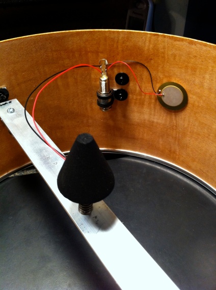
Next up was mounting my drum trigger cone that I bought to the mount. I placed a flat piece of aluminum across the drum to show where the top of the shell/bottom of the drum head would be, and then adjusted the elevator screw down to the right height. In this picture (Photo 22) you can see that I added a spring to provide some tension on the bolt so that it wouldn’t unscrew itself from the vibrations from drumming. You will have to set the height for all of these prior to soldering the wires or gluing the trigger down, or else the attached wires will not let you turn the screw.

Now we needed to attach the triggers to the drum, and connect them to a jack (Photo 23) so that they can be plugged into your drum machine/brain/interface. I chose to make my drums dual triggered, meaning that I would have a trigger for the drum head, as well as add a trigger to the side of the drum with double sticky-sided foam tape to pick up any hits to the rim of the drum. The top cone will be the drum head trigger mounted on the elevator screw, and the bottom trigger will be stuck directly to the inside of the drum.
The above photo also shows one of the issues I encountered that I hadn’t thought of. I’m not an electronics guy, but some of the piezos and some of the additional wiring I bought were of different gauges. I think this may have contributed to some electrical resistance issues, where when I went to set the sensitivity with the trigger and the module, some I had to really increase the sensitivity level. I would try to stick with the same type of wiring throughout the set next time.

Here is how the dual, 1/4″ jack (the same kind that you would use for a guitar, or an old set of stereo headphones) were wired to the triggers (Photo 24). The wires were attached, and then soldered into place. The longer tab was for the main drum trigger, the shorter tab was for the side/dual trigger, and both triggers were attached to the ground.

Here is the brand of stereo jack that I purchased for the project (Photo 25).

I needed a way to mount the stereo jack to the drum, so I purchased these 1/2″ Zinc clamps at the hardware store (Photo 26). I liked that they were rubber lined. I suppose a plastic clamp would work as well.

The jack was mounted pointing down using the screws for the tension rod mounts (Photo 27). I pointed them down so that the wire could be easily brought in under the drum and inserted into the jack. You could also drill a hole and mount them directly to the drum, but I didn’t want to have the cord sticking straight out of the drum. Nor did I want to drill another hole into the shell.
Here are both triggers and attached jack mounted to the drum (Photo 28).

Now to mount the toms to the stand. For the stands I used Sound Percussion brand cymbal stands. My first attempt at mounting the toms was to use a piece of zinc plated angle iron with holes, and bolted to the stand with a U-bolt. U-bolts were bought to mount the drums to the stand (Photo 29). This created a problem. They were too low, and the drums were flat and not at an angle. They also moved (pivoted) too much and bounced. This wasn’t acceptable. So I came up with a more sturdier option.

I went to the home improvement store and bought a piece of 1/8″ X 1″ angled aluminum, 4 feet in length. I cut them down to 20 1/2″ and marked the middle with black marker. I then drilled two holes for the U-bolt to mount to the cymbal stand (Photo 30), and two more holes for the bolts I would use to mount the drums.

For the drum mounting bolts, I chose 3/8″ X 12″ threaded rods (Photo 31). I bought two locking type nuts for each mounting rod. In the above photo, I placed two nuts facing each other to mark the halfway way point, then I used a saw and cut them into two pieces (Photo 32).

(Damn, this is turning into quite a post!)

Once I had my four mounting bolts, I decided to bend them slightly to allow the drums to be angled down like most traditional drum mounts. I accomplished the bend by using a piece of two foot long 1/2″ pipe, and just applying slight pressure until I bent the bolt.

To make sure they were all at the same angle, I placed the bolt up against the piece of angled aluminum, and measured the height (Photo 34).

Here are the four bent bolts with the locking nuts (Photo 35).

This shows the angled piece of aluminum mounted to the stand, and the bolts attached to the mount, with the drums mounted to the bolts (Photo 36). What is nice about the Sound Percussion cymbal stand is that there is a little ledge where the mount can rest, and won’t allow for the drums to slide down the stand. The drum on the right is the one I mentioned earlier that was 1″ inch smaller than the other three. You didn’t really notice, did you?

Another view of the bolts as they sit on the stand with the drums attached (Photo 37).

A view from the top side (Photo 38).

This would be the basic set-up for the drums (Photo 39). The “floor” tom is the same size as the snare drum, and also on a Sound Percussion snare stand.

You are probably wondering what the heck this is. Well, after getting the drums mounted with my new mount I found that they still bounced way too much for my liking. So I had to come up with another way to secure the tom mounting bracket to the stand. This picture (Photo 40) shows that I went and got some more flat aluminum to help brace the bottom of the mounting brace to the cymbal stand.

After measuring the bracket and drilling the holes, I bent them to the shape I needed (Photo 41).

I now had four bracing brackets of similar shape and length (Photo 42).

Back to the hardware store to buy a bigger version of the clamps, this time 1″ zinc and rubber clamps (Photo 43). These were needed to secure the bottom of the brace to the cymbal stand.

This is the final mounts bolted in place (Photo 44). The thing was rock steady.

Now, let’s talk the kick drum! Hooray! Since the drum was bigger, and would be facing outward, I didn’t want the internal stuff to be seen. So I purchased double the lug mounts and added them all around for a total of 8 for each side. The trigger mounts were done in the same way that the other drums were done. The difference would be that the cable jack would be mounted directly through the shell, as you can’t run a wire through the head. The above photo (Photo 45) shows how the legs were made. I once again made a trip to the home improvement store and bought some 4 foot zinc coated rods. The rods were easily bent in the vise, and at such an angle in which they would still run through the mounts attached to the side of the drum. I also ran over to the shelf section and bought some little white rubber end caps for the ends of the rods, so they would stay in place and not scratch the floor.
Another issue about this kick drum was how to attach the kick pedal to it. Normally the kick pedal attaches to the drum as it sits on the floor, but this drum is elevated. In the end, seeing that the drum set was on carpet, I let the pedal just sit on the carpeted floor. The kick pedal I have has some spikes on the bottom to dig in and keep it from moving with each step on the pedal. It works for now. May have to come up with something else in the future.

Here’s the cable jack, which I located on the lower portion of the kick drum (Photo 46).

Since I didn’t know I was getting an extra shell, I hadn’t ordered enough of the cones. But the company that I bought the cones and piezos from also threw in some of this cone foam material, so I used it to fabricate a trigger. I basically stuck a piezo on one of the blocks with the double-sided sticky foam tape, and then cut extra foam tape for the corners to attach the other piece (Photo 47).

Here’s an interior look at the trigger and cable jack (Photo 48).

I mounted a black Pearl resonant head on the outward facing side of the kick drum, and guess what? It resonated. Even with the mesh head on the other side, it was making an audible sound. So I added some adhesive foam that is used to help seal windows and doors to deaden the sound (Photo 49). I also mount this stuff on my acoustic drums as well.

After stepping back and taking a look at the mounted drums, I decided I didn’t like the look of the threaded posts, so I went back to the home improvement store and found some black plastic hose to hide the posts and give it a finished look (Photo 50).

Here is pretty much the finished set (Photo 51). Lots of things I left out that I need to fill you in on. After the lengthy drum build, I was to the point where I just wanted to be done and play the damn thing. So, instead of fabricating cymbals, I went and bought some Pintech electronic cymbals. They are pretty much plug and play, with dual trigger features as well (dome and ride, and crash and choke). The hi-hat are Pintech as well, mounted on a Sound Percussion hi-hat stand. Pintech supplied a sort of rheostat/potentiometer kind of a deal, that is supposed to mimic the hi-hat open closed sound as you open and close the pedal. It is not the best operating piece of the equipment. I may in the future replace it with just a foot pedal style switch instead.


The above is a few other things I purchased for the set. Sound Percussion was so cheap and easy to get that I stayed with that brand, and I found them to be pretty good entry-level stuff. I bought most of the non-fabricated stuff at my local Guitar Center.
The drum module that I used was the Alesis DM10. The jury is still out on this. I chose it because it seemed to be what most DIYer’s used, but it is a little hard for me to program it the way I want. Most people think that it is pretty much plug stuff in and start pounding away. In reality, with electronic drums there is a lot of tweaking involved.
CONCLUSION
I really enjoyed the build process of planning and creating my own set of electronic drums. Are they perfect? No. I have a cross-talk issue with a couple of drums (if you hit one of the drums you can hear a faint cymbal sound as well).
And was it cheaper? You would think so, right? Yes and no. The brain/module was still close to $900, and all of the hardware, parts and equipment add up real quick. If you are really into DIY, or really desire to design something unique, then it might be worth it to you. If not, you would probably be better off getting a factory made kit from Yamaha, Alesis, Roland, etc.
I really learned a lot from other builders who shared their projects. I hope that maybe someone else heading down the path I took, can look at the above and gets some ideas to incorporate into their own builds. Have fun!
LIST OF PURCHASED ITEMS
Okay, so it might be lacking a few things, but here are some of the major things I bought for the build.
(2) 14” and (4) 12” – 5 ply Keller Maple drum shells from Keller that I found listed as overstock on eBay for $160.
4) 12” Pearl Mesh Silent heads, (2) 14” Pearl Mesh Silent heads, (1) 14” Remo Ambassador Black head.
(1) set of piezo triggers, with foam cones from eBay seller power impulse. The set includes 5 piezo triggers with attached cones, 1 snare designed pro-sensing piezo with cone, and 5 singular piezos for secondary sensing.
(3) 14” chrome hoops, (4) 12” chrome hoops, (48) chrome lugs, (48) 2” tension rods, and (6) 10.5 mm chrome tom mounting brackets from drumfactorydirect.com
Purchased hardware at Home Depot to for the piezo mounts and to mount the drums.
Purchased hardware at Home Depot to for the piezo mounts and to mount the drums.
Purchased the Sound Percussion two boom cymbal stand deal and a S/P snare stand from Guitar Center due to a large online back order of the boom stands. GC had them in stock.
Purchased (10) additional 35 mm Piezos from UFO Drums on eBay. Needed extra triggers for the extra drum and cymbals(?).
Purchased several hardware items to be used as mounts for the triggers. Included are elevator bolts, which have a flat base to which the cone trigger can be mounted. Nuts and rubber washers were also purchased.
Purchased the Alesis DM10 Module and also another 14” mesh head, and a Sound Percussion snare stand from Musicians’ Friend.
TOTAL COSTS (IN 2011 PRICES)
$160 – (6) Keller 5 ply Maple drum shells, includes requested cuts and shipping
$74 – (7) Drum heads from Musician’s Friend
$88 – (11) piezos with cones from eBay power impulse (includes overseas shipping)
$267 – (8) drum hoops, (56) lugs and tension rods, (6) brackets
$60 – Corner braces, U-bolts, Aluminum flat plate and angle plate
$120 – (2) Sound Percussion boom style cymbal stands, (1) Sound Percussion snare stand.
$64 – (10) 35mm Piezo Triggers from UFO Drums (eBay)
$18 – (7) elevator bolts, plus nuts, and bolts for bracket mounting from Lowe’s
$820 – (1) Alesis DM10 drum module
